
A complete guide to solving PicoDVI image display problems
Displaying text with PicoDVI is relatively straightforward, but once you step into image rendering (BMP → RGB565), unexpected issues begin to appear. In my case, two major traps consumed a significant amount of time:
“色の反転」と「エンディアンの解釈」という2つの罠にハマり、かなりの時間を費やすことになりました。
This article documents the full troubleshooting process and the final working configuration.
1. First Failure: Green Turns Into Cyan
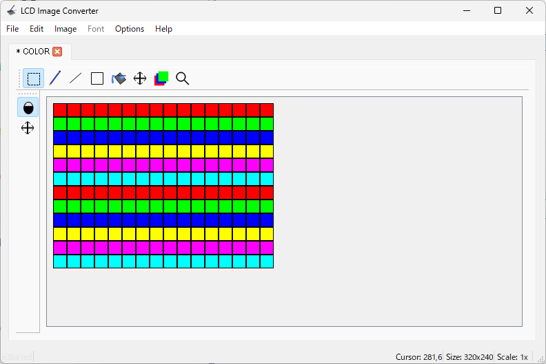
I started by converting a BMP image using lcd-image-converter and displaying it via PicoDVI. A simple test image—pure green (R:0, G:255, B:0)—unexpectedly appeared cyan on the screen.AI tools suggested checking big‑endian vs little‑endian, but switching the settings didn’t fix the issue. To isolate the cause, I generated manual RGB565 test data to eliminate tool‑side errors.
2. Root Cause #1: Color Inversion via invert_diffpairs
Through step‑by‑step testing (starting with monochrome, then adding colors), I discovered the first culprit:
invert_diffpairs inside dvi_serialiser_cfg
cpp
const dvi_serialiser_cfg my_dvi_cfg = {
    .pio = pio0,
    .sm_tmds = {0, 1, 2},
    .pins_tmds = {12, 16, 18},
    .pins_clk = 14,
    .invert_diffpairs = false   // ← This caused the color inversion!
};
If this flag is incorrect, TMDS signal polarity flips, causing colors to invert at the hardware level.
Fixing this finally stabilized the color output.
3. Root Cause #2: The True Byte Order of RGB565
Next, I investigated the 16‑bit RGB565 byte order used by PicoDVI.
Using custom test patterns with display.drawRGBBitmap(), I confirmed:
✔ PicoDVI expects RGB565 data in little‑endian order
(lower byte first → upper byte)
This matched the behavior described in the PDF:
“16bitテーブルの値が下位バイト·上位バイトの順で格納されているときに正常に表示される”
This meant the conversion tool needed to output data in the same order.
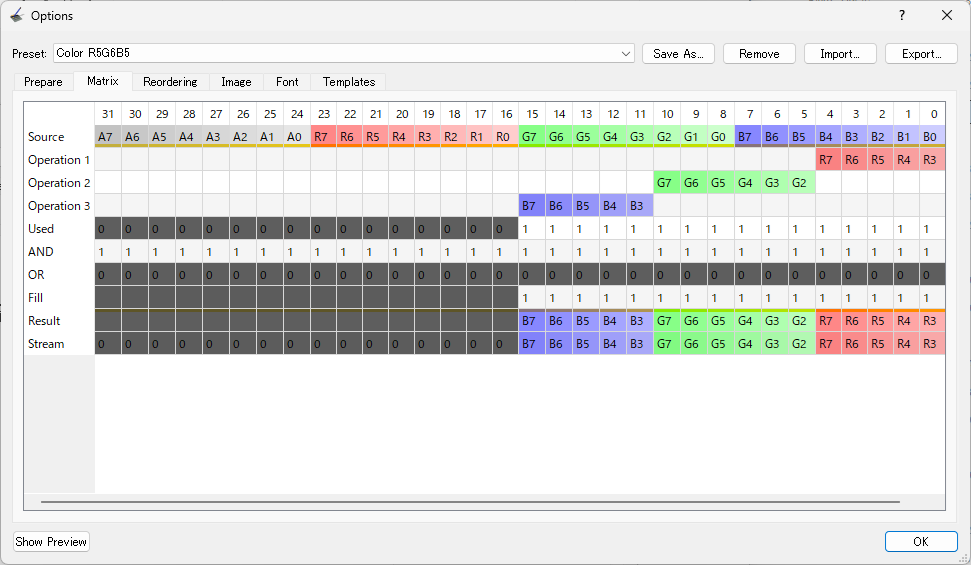
4. Final Adjustment: Correct lcd‑image‑converter Settings
Once both issues were identified, I created red/green/blue BMPs and tuned the tool settings until they matched the working test data.
Required settings:
✔ Byte Order → Big‑Endian OFF / Little‑Endian ON
✔ Matrix → Adjust Operation 1 / 2 / 3
To ensure R/G/B bits map correctly into the 16‑bit stream.
✔ Scan Direction → Top to Bottom / Forward
Matches PicoDVI’s expected pixel order.
After applying these settings, the displayed colors finally matched the original BMP.


5. Summary
By addressing:
- invert_diffpairs (hardware-level color inversion)
- RGB565 byte order (lower byte first)
- lcd-image-converter matrix and byte-order settings
I achieved perfectly accurate RGB565 image rendering on PicoDVI.
This troubleshooting flow is valuable because many PicoDVI users worldwide encounter the same traps, yet clear documentation is scarce.

コメント