
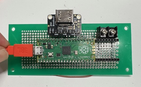
I tested HDMI output using a Raspberry Pi Pico combined with the Adafruit DVI Breakout Board. During the setup, I used two AIs (AI1 and AI2) as “thinking partners.” AI1 suggested that the standard Pico (non‑W) would be more stable than Pico W and recommended using a short 10 cm HDMI cable for signal reliability.
After several trials, the program structure proposed by AI2 finally led to a successful display output. This article documents how I overcame initialization failures and achieved stable HDMI output.
Hardware Used
- IoT Microcontroller: Raspberry Pi Pico W Although this model includes wireless features, only HDMI/DVI output was used in this project.
- DVI Output Board: Adafruit DVI Breakout Board Outputs DVI‑D signals through an HDMI connector.
- Display: Industrial 10.1‑inch capacitive touch monitor
Software Environment
- Development Environment: Arduino IDE 2.3.4
- Library: PicoDVI (Adafruit Fork) Uses RP2040’s PIO (Programmable I/O) to generate DVI signals.
- Project Name:
ras_dvi.ino
Technical Notes
1. Avoiding Initialization Failure
If `display.begin()` fails (resulting in a blinking LED state), the resolution settings and the stability of the system clock (252 MHz) are the key factors.
Setting the resolution to 320×240 (16‑bit color) reduced memory usage and stabilized startup.
2. Pin Assignment Optimization
From the PDF:
Precisely specify GPIOs 12, 14, 16, and 18. Pay attention to potential interference from adjacent pins on the differential pair (D+/D-).
Correct TMDS pin mapping is essential:
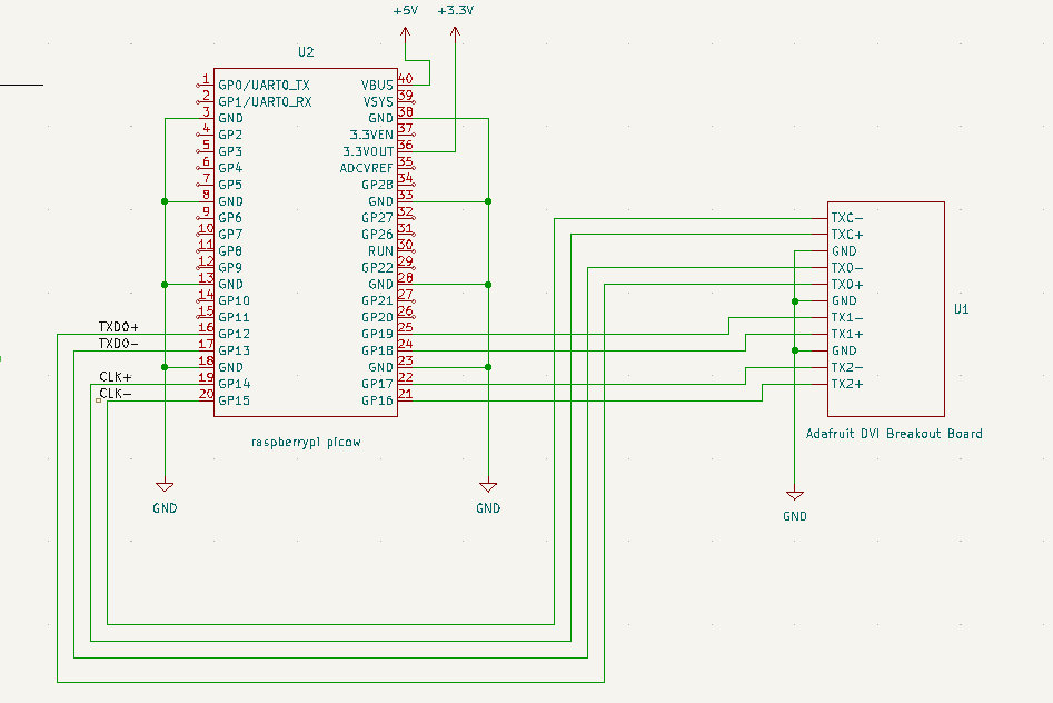
- TMDS0 → GPIO 12
- TMDS1 → GPIO 16
- TMDS2 → GPIO 18
- Clock → GPIO 14
Also, toggling invert_diffpairs was necessary depending on wiring.
3. Debugging the Clock Frequency Trap
From the PDF:
“I set the frequency to 275 MHz, but the microcontroller itself froze, and not a single line of the program executed.”
Clock behavior findings:
- Up to 250 MHz: Program runs, but DVI timing (640×480 equivalent) does not sync → no display.
- 252 MHz (Golden Value): Required for 320×240 pixel doubling → display finally synchronized.
- Lesson Learned: Higher clock ≠ better. Correct video timing (e.g., 252 MHz) is the key to stable DVI output.
Circuit Diagram
The PDF includes the full pin mapping between Raspberry Pi Pico and the Adafruit DVI Breakout Board. (You can embed the diagram image here in your WordPress article.)
Final Working Code
cpp
#include <PicoDVI.h>

const dvi_serialiser_cfg my_dvi_cfg = {
  .pio = pio0,
  .sm_tmds = {0, 1, 2},
  .pins_tmds = {12, 16, 18}, // Blue(D0), Green(D1), Red(D2)
  .pins_clk = 14,
  .invert_diffpairs = true
};

DVIGFX16 display(DVI_RES_320x240p60, my_dvi_cfg, VREG_VOLTAGE_1_20);

void setup() {
  if (!display.begin()) {
    pinMode(LED_BUILTIN, OUTPUT);
    while (1) {
      digitalWrite(LED_BUILTIN, HIGH); delay(100);
      digitalWrite(LED_BUILTIN, LOW); delay(100);
    }
  }

  display.fillScreen(0x0000);

  String text = "faithit";
  int textSize = 3;
  display.setTextSize(textSize);

  int16_t x1, y1;
  uint16_t w, h;
  display.getTextBounds(text, 0, 0, &x1, &y1, &w, &h);

  int centerX = (320 - w) / 2;
  int centerY = (240 - h) / 2;

  display.setCursor(centerX, centerY);
  display.setTextColor(0xFFFF);
  display.print(text);
}

void loop() {}
Summary
- PicoDVI requires precise clock settings (252 MHz)
- 320×240 resolution is stable and memory‑efficient
- Correct TMDS pin mapping is essential
- Initialization failures often come from incorrect clock or timing
- Short HDMI cables improve signal stability
This project demonstrates how RP2040’s PIO can reliably generate DVI signals with the right configuration.

コメント